
A single 120-volt AC sump pump plugged into a wall outlet does not protect a finished suburban basement from a severe storm. The atmospheric conditions that produce torrential downpours are the exact conditions that knock trees into distribution lines, drop local grid power, and silence home Wi-Fi routers. When the power cuts out, an unbacked primary pump stops instantly while ground hydrostatic pressure continues driving thousands of gallons of water toward your foundation footing.
Preventing a catastrophic basement flood requires three distinct physical layers: mechanical pumping redundancy, independent electrical energy storage, and out-of-band alert delivery. While an automatic main shutoff valve protects against pressurized indoor plumbing leaks, it cannot stop stormwater rising from an outdoor water table. If your primary pump jams, burns out, or loses electrical current, only a dedicated secondary DC pump and a staged float switch can prevent water from breaching the pit rim.
Sump pits combine 120-volt AC line voltage, mechanical impellers, and standing groundwater. Always disconnect electrical power at the main service panel before inspecting a basin or touching wiring. Never step into standing water to access electrical equipment. Because discharge plumbing, backflow prevention, and dedicated branch circuits involve building codes and flood safety, verify requirements with your local Authority Having Jurisdiction (AHJ) and engage licensed plumbing and electrical professionals where required.
This guide was fact-checked on October 19, 2026 against the International Residential Code (IRC Chapter 33, Section P3303), the National Electrical Code (NEC Article 430), and Sump and Sewage Pump Association (SSPA) installation guidelines.
The smart plug trap: why induction motors destroy 15-amp relays
One of the most dangerous DIY smart home mistakes is plugging a primary sump pump into a standard $15 Wi-Fi smart plug to monitor power usage or track cycles. It appears harmless on paper. A 1/3-horsepower submersible pump typically draws within 7 to 10 running amps at 115 volts, which sits well below the 15-amp resistive rating printed on consumer smart sockets.
Inductive electrical motors do not behave like resistive incandescent light bulbs or space heaters. Under NEC Table 430.248, standard single-phase 115-volt residential motors carry full-load current (FLC) ratings of 7.2 amps for 1/3 HP and 9.8 amps for 1/2 HP for circuit sizing purposes. In real-world equipment, manufacturer nameplates reflect specific motor designs; for example, the popular 115-volt Zoeller Model 53 (“Mighty-Mate” 0.3 HP) lists a full load rating of 9.7 amps on its official technical data specification.
Crucially, these running figures do not reflect startup inrush. When a split-phase or capacitor-start induction motor energizes from a complete standstill, it draws a severe initial current spike—known as Locked Rotor Amps (LRA) or starting inrush—that can reach several times its continuous running current for several hundred milliseconds while the rotor breaks static inertia:
Single-Phase Motor Startup Inrush:
[Rest: 0A] ---> [Startup Inrush Surge (Several Times Running Amps)] ---> [Running Load: 7.2A–9.8A FLC (NEC Table 430.248)]
                                        ^
                    Inductive arcing stresses general-purpose resistive relays
Homeowners often confuse a smart plug’s certification standard with its actual motor load rating. Most off-the-shelf consumer smart plugs are certified under general-purpose control and adapter standards like UL 60730-1 or UL 498A, carrying ratings specified primarily for resistive loads (such as 15A resistive, 1800W). While certain specialized industrial relays or heavy-duty smart switches carry explicit fractional-horsepower motor ratings, standard consumer smart plugs lack the inductive contact ratings required for motor-operated water pumps (which are governed by standards like UL 778). In fact, most consumer smart plug manuals explicitly advise against connecting motor-driven safety appliances or flood-prevention equipment. The repeated electrical arcing generated by high inductive motor startup surges quickly erodes miniature PCB-mounted contacts, risking two failure modes:
- Relay contacts weld shut in the closed position: The plug cannot disconnect power, disabling remote control while generating internal contact heat.
- Relay contacts burn out or weld open: The electrical circuit breaks permanently. The next time groundwater fills the basin, the pump receives zero voltage, and the basement floods silently while the smartphone app reports the plug as “online.”
Even if a smart switch carries a rated motor allowance, placing any consumer smart plug inline with a primary sump pump introduces an unnecessary series point of failure—susceptible to firmware glitches, accidental app shutoffs, and relay wear. Sump pumps should always plug directly into a dedicated, unswitched 15-amp or 20-amp branch circuit (with GFCI protection per NEC Article 210.8(A)(5) unless local amendments specify otherwise). To track pump cycles and power consumption safely, use non-invasive current-sensing CT clamps (such as whole-home panel monitors) that wrap around the circuit wire without placing an inline mechanical relay in the path of the pump.
Plumbing geometry: staging dual pumps and check valves in a basin
Redundancy fails if both pumps cannot discharge water independently. A secondary 12-volt DC backup pump squeezed into an existing basin must be hydraulically and mechanically separated from the primary 120-volt AC pump.
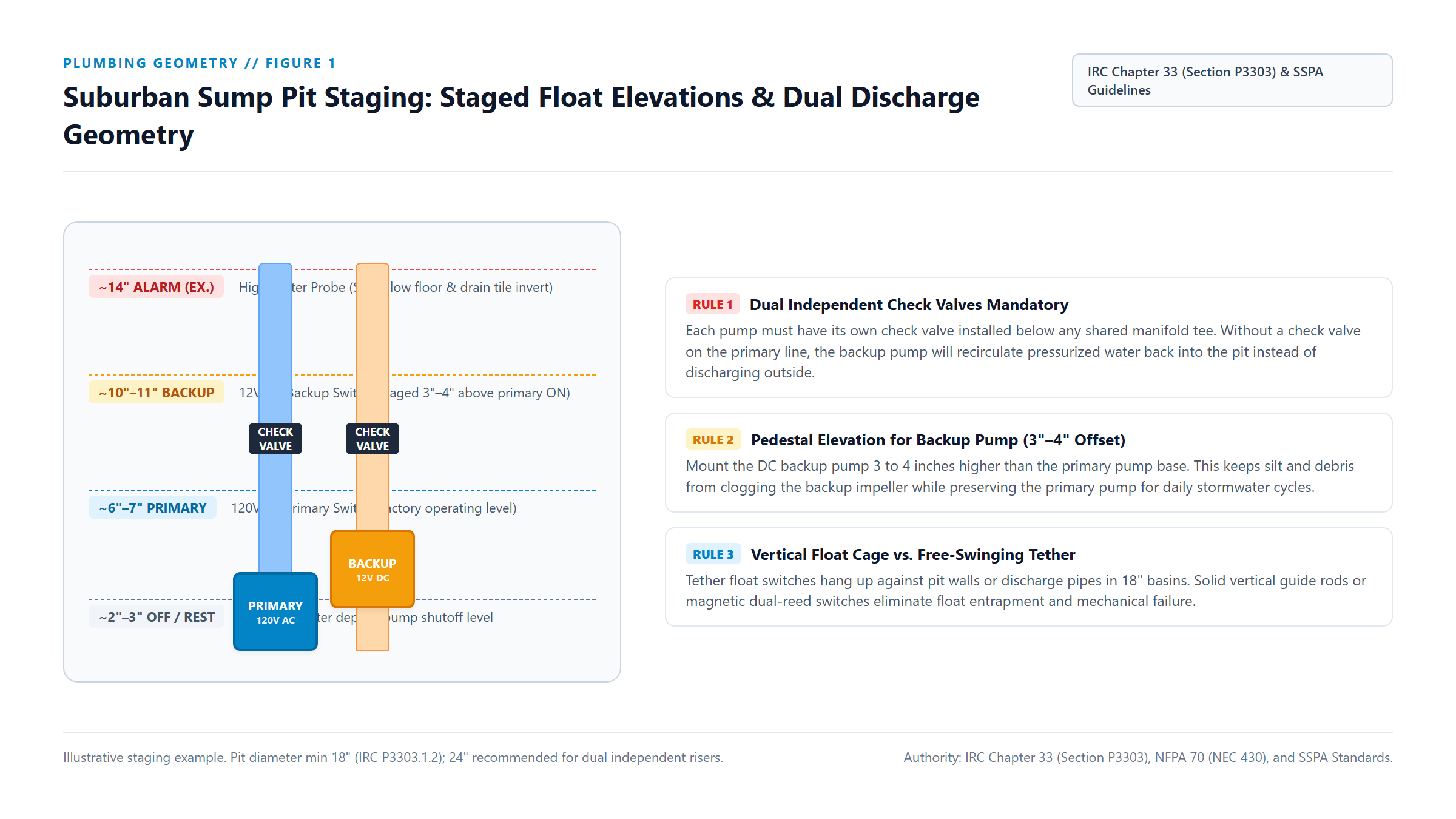 Figure 1: Illustrative cross-sectional staging geometry for an 18-inch to 24-inch sump basin. Staggering float trigger levels (shown here with typical ~6”, ~10”, and ~14” offsets) and installing dual independent check valves below the discharge tee prevents hydraulic looping. Always verify activation levels against your specific pump manual and basement drain tile depth. Diagram: The Smart Suburbanite Engineering Desk.
Under IRC Section P3303.1.2, a residential sump pit must measure not less than 18 inches (457 mm) in diameter and 24 inches (610 mm) deep, with a solid bottom to permanently support the pump and an accessible removable cover. While compact combination dual-pump packages can fit into an 18-inch pit, pump manufacturers and SSPA guidelines recommend a 24-inch diameter basin whenever installing two independent, full-sized cast-iron pumps. The larger diameter provides essential physical clearance for float arms and dual discharge risers without risk of binding.
When staging dual pumps inside the basin, follow four non-negotiable plumbing rules:
1. Dual independent check valves are mandatory
Never connect a primary pump and a backup pump to a single discharge line without installing an independent full-flow check valve on each vertical riser pipe, mounted below the combining wye fitting.
Under IRC Section P3303 and SSPA standards, if the primary check valve is omitted or fails to seat, the secondary pump will simply push pressurized discharge water backwards down the primary riser and through its open impeller, circulating water in an infinite loop inside the basin. The backup pump will run continuously until its 12V battery completely discharges, never dropping the water level in the pit.
2. Vertical staging prevents premature backup cycling
Set the primary AC pump on a solid brick or concrete paver 2 inches above the basin floor. This prevents the impeller from sucking in gravel, construction grit, or washed silt that accumulates at the bottom of the basin.
Mount the secondary 12V DC backup pump on an elevated bracket or separate brick 3 to 4 inches higher than the primary pump base. Stagger float switches so the backup switch is positioned approximately 3 to 4 inches above the primary switch’s activation level (for example, ~6”–7” primary ON, ~10”–11” backup ON), with the high-water alarm probe positioned at ~13”–14” (below the basement floor line and sub-slab perimeter drain tile invert). Exact activation heights must follow the pump manufacturer’s manual and the elevation of incoming foundation drain tiles to prevent water from backing up into footing drain systems.
3. Drill the 3/16-inch weep hole to stop air lock
When a submersible pump empties a pit, air can become trapped inside the volute chamber beneath the closed flapper of the check valve. When water rises again, the trapped air bubble prevents water from contacting the spinning impeller, causing the motor to spin helplessly without pumping a single drop.
Manufacturer manuals from Zoeller, Wayne, and Liberty explicitly require drilling a 3/16-inch (4.8 mm) hole angled downward at 45 degrees into each PVC discharge pipe, located between the pump discharge nozzle and the bottom of the check valve. This weep hole releases trapped air as water enters the pit, allowing immediate hydraulic prime.
4. Protect exterior discharge lines against winter freezing
In freeze-prone northern climates, check valves prevent water from returning to the pit, but water trapped in exterior discharge pipes outside the foundation can freeze solid. If the exterior pipe freezes, the pump will deadhead against ice and burn out. Install an exterior air-gap freeze-relief discharge fitting (such as an IceGuard bell) where the pipe exits the rim joist, allowing water to escape onto the grade if the buried drain pipe freezes.
Float switch mechanics: why tether balls fail in active pits
More than 60% of all sump pump failures are mechanical switch failures rather than burnt motor windings. The traditional free-swinging tether float—a buoyant plastic bulb anchored by a short electrical cord—is the least reliable mechanism for an active suburban sump pit.
Tether Float (High Jam Risk)          Vertical Caged Float (Reliable)
       |                                     |
    [ Cord ]                              [ Guide ]
       \                                     |
        [Float] ---> Wedges on PVC      [=====Float=====] (Slides purely on Z-axis)
                     or pit wall             |
In an 18-inch basin with two discharge pipes, power cables, and a battery sensor wire, a swinging tether ball requires a wide, unobstructed circular clearance arc of 18 to 24 inches. Under heavy storm inflow, swirling turbulence knocks the tether ball against the corrugated basin wall or wraps its cord around the discharge pipe. The switch wedges in the “OFF” position, allowing water to overflow the rim, or jams in the “ON” position, running the pump dry until the thermal protector trips.
For suburban reliability, choose between two superior switch designs:
- Caged vertical guide rods: The float moves strictly along a rigid vertical stainless steel or PVC rod, constrained within a plastic safety cage. Lateral water currents cannot deflect the switch into nearby piping, requiring less than 4 inches of horizontal clearance.
- Solid-state dual-reed magnetic or optical probes: Modern smart controllers (such as the Zoeller Z-Control or Moen Flo Sump) use microprocessor-monitored magnetic reed switches or optical liquid probes with zero external moving parts. Because they rely on solid-state electronics, they resist mineral encrustation and provide exact cycle timing telemetry.
Battery chemistry and sizing: AGM deep-cycle vs. LiFePO4
A battery backup system is only as dependable as the amp-hour (Ah) capacity, operating temperature, and chemical stability of its energy storage bank. Homeowners frequently miscalculate battery runtime by confusing continuous run time with intermittent storm cycling, or by assuming that a battery’s nominal nameplate rating represents 100% usable energy.
Nominal capacity vs. usable capacity
Lead-acid batteries (both flooded and sealed AGM) are rated at a nominal 20-hour discharge rate (C/20 at 77°F / 25°C). Discharging an AGM battery beyond 50% depth of discharge (DoD) causes rapid plate sulfation and shortens its operating life. Therefore, a standard Group 27 or Group 31 100Ah AGM battery provides roughly 50 to 60 amp-hours of safe usable capacity.
In contrast, Lithium Iron Phosphate (LiFePO4) chemistry allows safe discharging to 85% to 90% DoD without plate degradation, providing approximately 85 to 90 usable amp-hours from a 100Ah pack.
Continuous pumping vs. intermittent storm cycling
A typical 12-volt DC backup pump (such as the Zoeller Aquanot 508 or Wayne ESP25) draws between 10 and 14 amps under a standard 8-to-10-foot dynamic discharge head.
Because actual off-grid survival time depends directly on the specific pump model’s current draw at your home’s total dynamic head, local groundwater inflow rates, ambient temperature, and battery age, any runtime figures must be evaluated as conditional scenario estimates rather than fixed product performance ratings:
- Continuous pumping scenario: If heavy storm inflow matches the pump’s discharge rate so that the motor runs without cycling off, a 50Ah usable bank depleted at a continuous 12-amp load will be fully exhausted in roughly 3.5 to 4.5 hours.
- Conditional intermittent storm scenario: In moderate storm conditions where water enters steadily but allows the pump to cycle periodically—for instance, running for 15 seconds every 2.5 to 3 minutes (an 8% to 10% duty cycle)—average current draw drops substantially:
- Average current draw: (\approx 12\text{A} \times 0.083 \approx 1.0\text{A})
- Theoretical runtime: (\approx \frac{50\text{Ah}}{1.0\text{A}} \approx 50\text{ hours (under ideal 77°F laboratory conditions)})
However, that 50-hour laboratory calculation represents an idealized upper limit. Four real-world derating factors dramatically influence practical basement survival time:
- Ambient basement temperature: Basements and crawlspaces during spring rainstorms or winter thaws often hover between 45°F and 55°F (7°C to 13°C). Lead-acid chemical reaction speed slows in cold temperatures, reducing usable capacity by 15% to 25% compared to factory 77°F ratings.
- Inflow volume and higher duty cycles: In intense downpours where the pump cycles for 20 seconds every 1.5 minutes (a 22% duty cycle), average current draw rises to 2.6 amps, cutting usable battery runtime to roughly 18 to 22 hours.
- Battery aging: After 2 to 3 years on float charge, an AGM battery typically retains only 70% to 80% of its original capacity.
- Controller standby draw: Telemetry radios, high-water audible alarms, and charger monitoring circuits consume a continuous parasitic standby current (typically 50mA to 200mA, adding 1.2Ah to 4.8Ah of drain every 24 hours).
When all derating factors are combined under an assumed 8% to 10% duty cycle, a fresh 100Ah AGM battery yields a conditional working estimate of roughly 15 to 40 hours of intermittent storm protection—not a guaranteed product specification. If your area experiences extended multi-day outages or high hydrostatic water tables, do not rely on a single battery: install dual parallel AGM batteries (200Ah), pair with a high-capacity LiFePO4 bank with lithium-compatible charging, or integrate a standby generator or home battery storage system as discussed in our whole-home backup guide.
| Battery Metric | Flooded Deep-Cycle Lead-Acid | Sealed AGM (Absorbent Glass Mat) | Lithium Iron Phosphate (LiFePO4) |
|---|---|---|---|
| Usable Depth of Discharge | 50% (~50Ah usable from 100Ah) | 50%–60% (~50–60Ah usable) | 85%–90% (~85–90Ah usable) |
| Cycle Life to 80% Capacity | 200–300 cycles | 300–500 cycles | 2,000–4,000 cycles |
| Typical Calendar Lifespan | 2 to 3 years | 3 to 5 years | 8 to 10 years |
| Maintenance Requirements | Monthly distilled water checks; toxic off-gassing | Fully sealed; zero fluid maintenance | Fully sealed; integrated BMS protection |
| Cold Basement Performance | Moderate capacity loss (~20% at 45°F) | Stable discharge in unheated basements | High discharge; cannot charge below 32°F (0°C) |
| Charger Compatibility | Standard constant-voltage trickle | Multi-stage AGM profile | Dedicated CC/CV lithium profile required |
While Lithium Iron Phosphate (LiFePO4) offers superior calendar life and double the usable runtime per pound, verify that your backup controller includes a dedicated lithium charging profile. Connecting a LiFePO4 battery to an older lead-acid trickle charger will result in chronic undercharging or premature Battery Management System (BMS) shutdown. Furthermore, if your sump pit is located in an unheated, freezing crawlspace, ensure the lithium battery incorporates internal low-temperature charging protection to prevent permanent cell plating.
Outage resilience: why Wi-Fi fails and cellular alerts survive
A smart sump pump monitor that relies exclusively on home Wi-Fi creates a single point of failure. When a severe weather system knocks down utility lines, your grid-tied home internet modem and Wi-Fi mesh router lose power instantly. Unless your networking gear is isolated on a dedicated Uninterruptible Power Supply (UPS) as detailed in our home Wi-Fi optimization guide, all local Wi-Fi water pucks and cloud-connected pump monitors become unreachable.
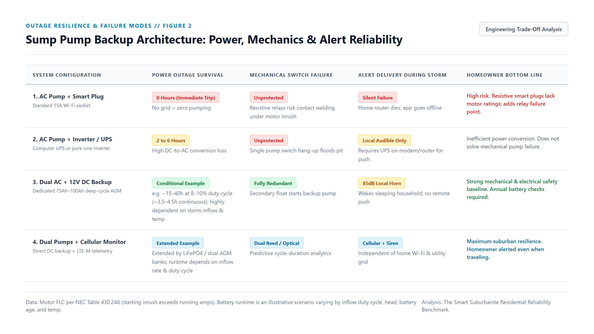 Figure 2: Architecture comparison across four residential backup configurations. Combining dual pumps with cellular (LTE-M) telemetry provides independent warning capability when both grid electricity and municipal broadband fail. Analysis: The Smart Suburbanite Engineering Desk.
True storm resilience requires a layered notification architecture:
- A local high-decibel audible horn (85dB to 90dB): Remote smartphone notifications are useless if you are asleep upstairs and your phone is set to “Do Not Disturb.” A battery-powered mechanical buzzer mounted on the basement wall wakes household occupants immediately if water reaches the emergency high-water threshold.
- Out-of-band cellular telemetry (LTE-M / NB-IoT): Modern enterprise-grade residential monitors (such as PumpSpy or cellular-equipped Flo controllers) incorporate internal rechargeable battery backups and dedicated cellular radios. When the power grid and home broadband collapse, the controller transmits power failure, pump cycle, and high-water alerts directly to cell towers.
- Predictive cycle-duration analytics: A smart monitor should not wait for water to overflow the rim before alerting you. By measuring how many seconds the pump runs during each discharge cycle, intelligent controllers can flag hydraulic anomalies. If a primary pump normally empties the pit in 14 seconds, but suddenly runs for 48 seconds, the system flags a partial discharge pipe obstruction, a sticking check valve, or exterior line freezing long before water breaches the basement floor.
If you have already invested in a whole-home battery system or standby generator, your primary 120V pump will continue running during an outage. However, generator power does not protect against a cracked impeller, a tangled float switch, or a locked motor. A secondary 12V DC pump remains an essential mechanical fail-safe regardless of how much whole-home electrical backup you maintain.
Homeowner decision framework: choose your protection tier
Match your sump pit upgrades to your home’s topographical risk, finished basement equity, and travel schedule:
Tier 1: Mechanical baseline upgrade ($150–$300)
- Best for: Unfinished storage basements with low water tables and active homeowner presence.
- Actions: Replace existing tether float switches with caged vertical guide rods. Inspect and replace noisy swing check valves with spring-loaded quiet rubber check valves. Drill a 3/16-inch weep hole. Add an independent, 9-volt battery-powered 90dB high-water alarm puck set 2 inches above the primary switch.
Tier 2: Redundant dual-pump combination ($800–$1,400)
- Best for: Finished basements, homes with seasonal spring flooding, or suburban neighborhoods with frequent storm-related power flickers.
- Actions: Install a pre-plumbed dual-pump system combining a 1/3 HP or 1/2 HP cast-iron primary AC pump with an elevated 12V DC backup pump. Plumb dual independent check valves. Connect a sealed 100Ah AGM deep-cycle battery housed in a clean poly enclosure. Verify the primary pump sits on an unswitched, dedicated circuit.
Tier 3: Connected cellular telemetry ($1,500–$2,200)
- Best for: High-value finished basements, frequent travelers, or homes in flood-prone clay soil regions.
- Actions: Combine Tier 2 dual pumps with an LTE-M cellular smart telemetry controller. Install solid-state magnetic reed or ultrasonic water level sensors. Configure remote text and phone call alerts for power loss, battery voltage degradation, pump run-time anomalies, and high water. Plug home network modems into a minimum 1500VA battery backup.
Semi-annual maintenance checklist
Perform this 10-minute mechanical audit twice each year (in early spring before snowmelt and in late autumn before ground freeze):
- Slow-pour bucket test: Slowly pour 5 gallons of water into the basin until the primary pump engages. Verify the vertical switch rises smoothly without rubbing the pipe, that the motor empties the pit within 15 to 20 seconds, and that the check valve closes quietly without water hammering.
- Air-relief inspection: Check that water squirts cleanly from the 3/16-inch weep hole while the pump runs, verifying the hole is free of mineral scale or mud.
- Backup pump manual trigger: Lift the secondary backup pump float switch manually. Verify the DC motor starts immediately, that the alarm buzzer sounds, and that discharge water does not push back down the primary line.
- Battery health verification: Disconnect AC power to the backup charger. Use a digital multimeter to measure battery resting voltage: a healthy 12V AGM battery must read at or above 12.6 volts (100% state of charge). If voltage drops below 12.1 volts under resting conditions, replace the battery bank immediately.